Introduction
DUECA/DUSIME has been running for over 20 years now, and previous examples in the documentation have used older versions of the API. You can still use this API, sometimes with warnings, but it would be nice to have an extremely simple example with current "modern" DUECA, and that is given in this page.
We keep things simple in this example. Only one new module and a single new channel object is created, for the rest we use ready-made modules. This simple simulation uses:
- A standard joystick (or a gui alternative), to get inputs to the simulation. For the joystick interaction, we will use the available FlexiStick module. In terms of DUECA programming, FlexiStick is a beast, and we will not discuss how it is made, just how we can use it.
- We create a new UFODynamics module, which will implement extremely simple motion, with a rigid-body "vehicle" that can rotate with the inputs of the joystick, and can move forward and back. It floats in the world, so there are no complex contact dynamics.
- To link the UFODynamics, we create a Dueca Channel Object, or DCO, which defines what kind of data we get from the stick and read in the UFODynamics module. Actually, to simplify the workflow, we will make this one first.
- To see what we are doing with the dynamics, we will use the WorldView module for a 3D view of the world. WorldView is another one of those all-out DUECA beasts, which means that it can in most cases be configured to do what we want without programming or modification.
To investigate the support DUECA/DUSIME can give, we will look into some capabilities for enhancing a simulation. The FlexiStick can record its output (the joystick or screen input) and play that back, with DUSIME replay support. Now a good simulation should be deterministic; given the same input and starting position, the same output should result. The starting position is in this case determined by the state of our UFODynamics, to record and control that, we add initial condition facilities to the UFODynamics, at any moment its state can be saved into a snapshot, and when the simulation is not running, we can load from the snapshot.
After the simulation has been made, we look at a few more things:
- A mock set-up, in which we distribute the simulation over two DUECA nodes. This simulates running parts of your process on two computers.
- DUECA's timing overview, which shows the synchronization and timing of DUECA's nodes, and gives a summary of timing performance.
- DUECA's activity view, which enables us to take snapshots of DUECA timing, and inspect in depth what runs when.
- The channel overview, which enables inspection of channels (who writes what data, who reads it), and inspection of data in the channel.
- The DUSIME initial state control, for snapshot taking and re-loading.
- The DUSIME record and replay control, with which we can record a running simulation, and then later reload and replay that simulation.
- The net use overview, which shows the load on the network communication.
- DUECA's log files, startup blurp and error output.
- How to get script instructions on using module and other DUECA components.
- A simple program, dueca-channeldot, which can create a visual representation of your simulation from the logs.
If you want to explore a bit further, and look at how you could create multiplayer simulations with DUECA, you can check out the sequel More Simple Simulation.
Setting up
I assume you have the dueca packages installed on a (real or virtual) Linux computer, and can open a terminal window.
In this example we use dueca-gproject to set up the new project. We first need a playground somewhere, on a local or remote git repository. If you have access to a gitlab, github or similar site, you can create a completely empty repository there. If you want to play around locally, create an empty "upstream" repository by typing in the terminal (I am using the prompt [enter]$ here, your prompt might look a little different):
If you created a repository like this locally, it will be at a location on your computer, let's make a shell variable to have this location:
If you created the repository somewhere else, use that URL. Let's also indicate where we later can find the FlexiStick and WorldView projects from which we want to borrow the stick and worldview code:
This code is available in the public dueca repository on github. If you don't have an account there, you may access the code through https instead:
Creating the new project
Now we can create the initial project, we will collect our projects in a folder dapps (DUECA Applications) in the home folder:
Now enter the project folder. This is where your project-specific code, the configuration for the project, and datafiles live.
We see here the following:
- A folder build, where later the built executable will appear
- A CMakeLists.txt file, to generate the main build configuration, which uses cmake
- A folder comm-objects, this will be the place for communication objects, also commonly called DCO objects, objects with data that can be sent around by DUECA.
- A file README.md, I trust you to modify this to your liking.
- A folder run, which is the place where run configurations are located.
There is one additional place with important stuff, and that is the hidden folder .config. It contains the project configuration information, we'll look there later.
Version control with git
The creation of the empty project was performed on git's default (master) branch. However, as we are now going to edit, modify and possibly mess up a bit this project, it seems wise to work on a dedicated git branch. Then after we are done we can maybe (if needed, I let that up to you) clean up the history a bit, and merge the result into master to get the final product.
We will use that branch from here on.
Borrowing modules
To get a good feeling and a head start, we can now borrow the FlexiStick and WorldView modules. Still from the project folder, run the following:
The script tells you what it does. Now what happened to your project folder? Let's have a look:
A folder with FlexiStick appeared one level up from the project folder. This is where the FlexiStick code now lives:
There is apparently a lot of stuff there. We don't need to inspect that all now. Let's go back to the project folder, and inspect what happened to the project configuration:
I forgot to mention some things about machine classes. Let's keep it simple for now, and say that we are developing code for machine class solo. This is the initial machine class for DUECA, and it stands for any development computer that you use to make your simulation. The config.cmake file is obviously for your build configuration, and it may adapt the build configuration for the machine class. For solo it is practically empty, it only says we are using the gtk3 toolkit for windowing.
The two other files in that folder are modules.xml and modules.xml~. This second one is a back-up with the previous version, created when we borrowed the FlexiStick module. Let's take a look:
As you can see, it is an XML file. It currently has only one module in there, flexi-stick, from the project at the FlexiStick.git URL. However, the dueca-gitscript project entered a URL alias here, dgrpub:///. This is done on the basis of the environment variable set earlier, which ended in _pub, in this way the modules.xml file does not need to be modified if ever the access to the URL from which you borrow FlexiStick changes, updating the environment variable will fix that.
When we borrowed the module, the dueca-gproject script pulled the code from the remote repository, and put it in an appropriate place. If we later would want to clone our project somewhere else, the dueca-gproject script will look at the appropriate modules.xml file to see which code is needed and from where this code can be obtained.
For the WorldView, we need several modules:
- The main WorldView module. This module will run all interaction with our simulation.
- A module OSGViewer, with an OpenSceneGraph backend. There are several back-ends in the WorldView project.
- A module SpecificationBase, which is needed by OSGViewer.
- Some 3D models to show something in our view. We borrow module icy-world from WorldView for that purpose.
Let's do this:
You can see for yourself in the modules.xml file what happened. We borrowed icy-world as a pseudo module, with this we indicate that this module has no (C++) code, and CMake will not try to use it in building an executable.
Intermezzo, what do we have now?
Let's check the current status of our project. We borrowed one module from the FlexiStick project, and three modules from WorldView. Along with the modules, the dueca-gproject script also pulled in the comm-objects folders from these projects, since presumably the modules in WorldView and FlexiStick rely on the communication objects defined there. The dueca-gproject script analysed that dependency, and pulled out the relevant folders.
Although, without a link between the joystick input and the 3D view on the screen, the simulation now will not produce anything useful, we can try compiling the project, to verify that we have all needed software. Enter the build folder, configure the project, and then build it:
Your output may not look that perfect. The modules use a number of libraries, and you might need to install these on your computer. The cmake step will warn you when it is missing software, use your package manager to install that software.
To simplify these steps a bit, you can also ask the dueca-gproject script to configure and build your code for you. When using this, you do not need to enter the build folder first, simply call this from any folder in your project. To get, as in the above example, support for the debugger in your executable, just add a --debug flag:
# alternative for cmake and make calls:
dueca-gproject build --debug
As far as I can tell (things may change in the future), apart from the DUECA packages and their dependencies, you will need the following packages for a Debian-based Linux:
- libsdl2-dev
- libopenscenegraph-dev
So far so good. We created a new project, borrowed four modules, configured the project, and compiled all the code so far. Now for the difficult stuff.
Creating the communication object
Our simulation will have simple UFO-like dynamics (if at least we can decide on what that is like). Our UFO is like a ball that we can pitch (forward/backward tilt) roll (tilting to left or right) and yaw (rotating around to a new heading), all using a typical joystick with a stick that can tilt forward and back, left and right, and has twist axis for the yaw in the base. For moving around, we use the throttle on the stick, giving us forward motion in the direction of the current view point. Let's make a nice DCO (Dueca Communication Object) for that. DCO objects use a Scheme or Lisp-like syntax, with parentheses starting a command with zero or more arguments. A code generator will use this description to create C++ code for objects that can be packed and unpacked for transmission between DUECA nodes. Use the text editor of your choice to create a file ControlInput.dco in the comm-objects folder of your SimpleSimulation project, with the following contents:
Alternatively, you can use the script new-dco to create that dco file for you. As a minimum, new-dco requires the name of the DCO file, and the corresponding object that you are trying to create, and it produces a skeleton file to adapt to your liking:
You can also populate the object with more arguments:
Note the following:
- Comments are started with a semicolon (;)
- The Header command gives some text to include in the generated code, with the given format, these comments are nicely merged in the C++ header. The generated code for this DCO object will end up in build/SimpleSimulation/ufo-dynamics/ControlInput.[ch]xx. Take a peek there for how the C++ code looks.
- Comments before the defined object ("Communication .."), and before member definitions in the object are carried over into the generated C++ code, and they use the Doxygen format, so automatic document generation works.
- Each type that you use in a DCO object needs to be declared as such first, that is the reason for the (Type float) line.
Before we continue, add the communication object to the repository, and commit your work.
Look at the explanation of the code generator for more options.
Creating the new module
Next, we create the new module. This is a two-step process, first configure, with dueca-gproject, a folder for the module, and then create and adapt the code. We'll call the new module ufo-dynamics, make sure you start from the main project folder (SimpleSimulation/SimpleSimulation):
The CMakeLists.txt has information on how to build any code in ufo-dynamics, the comm-objects.lst file contains a list of communication objects that are needed by our new module. Let's add the ControlInput.dco file to that. Use your favourite text editor, and modify comm-objects.lst, until it looks like the following:
Now make the code for the new module. We are going to use a DUSIME module, since we will implement a simulation, and want to use typical simulation modes.
We had to enter the size of the state, and a description for the activity. In the past, it used to be important to indicate a correct size for the state, but that is no longer relevant, only the difference between 0 (no state, no snapshots) and non-zero matters. The non-zero answer given here will make sure that we will be able to capture and restore the Module's state, which we will use later.
This command added a header file and a body file, tell git to remember these:
Adding the communication to the new module
We want the new module to read the signals from the joystick and then tell the WorldView what the position is of the controlled UFO, so that the outside world can be correctly drawn. To make the communicated classes available, edit the comm-objects.lst file in ufo-dynamics, until it looks as follows:
Now, let's first set up the communication in the UFODynamics code. Use an editor on the UFODynamics header file, and add a read and a write token (uncomment the example, and change the names):
In DUECA, channels transport data between modules. A module can not directly access a channel, only through an access token. If you create a token, it will ensure that a channel end will be created locally, or it will create a connection to an already existing channel end.
Then make the matching changes in the UFODynamics.cxx file, to correct the constructor code. We know that (for our simulation), there is only one entry in the controls channel, with a datatype ControlInput, and we will configure it to be written as stream data; for each simulation time step, there will be current data available for that time step's time span.
The egomotion channel also has one entry, it gets written by our UFODynamics module, also as stream data. This channel will be used by the WorldView module to determine what should be the viewpoint on the world. The following code lists the creation of the two tokens:
Obviously, for our simulation, we would first have to read the joystick input, then calculate the dynamics for our model in ufo-dynamics, and with that outcome draw the view on the world with WorldView. In DUECA, that schedule is not explicitly specified, instead we specify "triggers". By triggering the activity for the dynamics (the do_calc object), on the data written by the joystick, it is ensured that the function UFODynamics::doCalculation is triggered whenever new data has been written. Here we do that with the setTrigger call:
In this case, this triggering waits only on the activities in one channel. If you would have wanted to wait for data in two channels, combined trigger conditions can be created, simply like:
The triggering actually looks at the times for which data is written, and logically combines these to trigger the activity. DUECA's scheduling facilities then actually run the associated function, with the priority determined by the PrioritySpec object passed to the UFODynamics constructor call.
The channel names are specified here with NameSet objects, in the form (entity, class, part). The 'entity' is the object to which the channel will belong, its name will be supplied later in the creation script. In many cases, the part is an empty string, but part can also be used to differentiate multiple similarly-named channels belonging to the same entity. 'class' is the type of data, note that this may be freely chosen, but for simple channels (one entry, with one specific type of communication object), it is customary to list the communication object type here. So the "class" of the r_controls token/channel is ControlInput, while the class of the datatype sent over that channel is also ControlInput. NameSets can also be written in a URL type fashion, for a contrived example see the following:
Channels can have multiple "entries", each entry represents a sort of slot in which a specific type of data can be written, and all data is time-tagged, so that the history (or part of the history) can be seen.
Multiple entries in a channel are sometimes used to for example represent all "other" vehicles in a simulation, but most channels have just one entry. In this channel, we expect only one entry (entry 0), so in the token construction call we specify that entry number and the parameter Channel::OnlyOneEntry. The data should be a continous stream (Channel::Continuous), which means that the data written there represents some continuous variable, rather than events or things that may happen or not happen at a specific time; Channel::Events is the main other option for channels. If the conditions set for the read token are not met (we specified continous data, and exactly one entry in the channel), the token will not become valid, and at least we will know our simulation is not correct yet.
The channel that we write to the WorldView likewise has only one entry, we again specify that with the Channel::OnlyOneEntry parameter. In this case, the class for the channel ("ObjectMotion"), is different from the (c++) class of objects we send over the channel ("BaseObjectMotion"). Here we can also give a label for the entry ("ufo movement").
Checking and running
Before DUECA will run a module's activities, it will try to check the status of the module, in this case with the UFODynamics::isPrepared call. Here you should verify that all conditions for continuing are met, in this case, checking that the tokens are valid; there is a handy macro for that:
For running our update loop, so once per time step, we use the doCalculation method. Something you need to be aware of is that DUECA is data-driven, and so if there is no data, there is normally no simulation. Whether you read the data or not is not critical, but our module must always produce data when it runs. For our initial set-up, we will add the reading of the control input, but not do anything with that data, and add writing of a fixed viewpoint to the WorldView. Here is how doCalculation should be modified:
Note that doCalculation is called with a TimeSpec object. This defines the time span for which this calculation is now running, which will be the same time span as for the data written in the channel from the joystick (which triggered this activity). When accessing the joystick with the r_controls token, that TimeSpec is again used. This ensured that we access the data with a consistent time.
The DataReader object u gives access to the data in the channel, through its data() function. At the end of the enclosing curly braces, the object u is destroyed, and the destructor call releases the access to the channel data.
The DataWriter is simular, this one uses the TimeSpec to determin for which time the data must be written.
We set the height to -3.0 m (WorldView uses aerospace conventions for axes, and the z-axis points down into the ground).
The doCalculation routine is called with a time specification ts. This specifies the time span for which the calculation should be carried out. Time in DUECA is divided into integer steps, one step, or a granule, has a user-definable duration. The activity do_calc is linked to the doCalculation routine. By specifying that this activity is triggered on the control channel, each data span written in the controls channel leads to a call of the doCalculation routine, with the span specified in ts.
Within the routine, that time span is used to retrieve the data from the controls channel, and to write the new data in the egomotion channel.
Trial run 1
Compilation
At this point, our code should be good enough to give it a trial run. The simulation is not yet in there, but there is input, triggering, and output. Let's try a compilation:
You will see that the build now automatically includes the ControlInput.dco file, and the new module we added. In most cases, c++ header and body files in a module are automatically included for compilation, if you don't want that, adapt the CMakeLists.txt files.
This creates an executable called dueca_run.x. It contains the module we developed, and the borrowed modules and code from FlexiStick and WorldView. To start a simulation with these, we need two (python) scripts, one that starts the DUECA code, and one that configures the simulation. A DUECA executable may be stuffed with modules and other code, but as long as you don't start up that code in a start script, it will do nothing. The contents of a DUECA executable can be inspected with:
You see a report on the various modules and objects built into this executable. Most of these come from DUECA libraries, but the first four are found in our new project.
Specific script instructions for a module can be obtained with:
This indicates that with the command dueca.Module with the given parameters, will create a ufo-dynamics module. There can be two parameters in this call, to set the timing (update rate) of the module, and one to add checks on the timing. You can try the other to modules (flexi-stick and world-view, and the object OSGViewer yourself. If you want, you can edit the last string in the UFODynamics::getParameterTable function to get a better description for the module.
Any parameters defined in the UFODynamics::getParameterTable function give the script language (Python or Scheme), access to variables or functions from the newly created class. This happens right after the constructor call. When all parameters are set, the UFODynamics::complete() call is called. For UFODynamics, that call is empty, but in many modules this is used for various purposes.
With that knowledge we can now move to the run folder for our platform, and start to adapt the start scripts for the simulation:
In a fresh run folder, you should see four files. The links.script should populate your run folder with files (usually symbolic links) that you need for running the simulation.
The clean.script reverses that action, and it should clean out your run folder from any generated or linked configuration files.
The file dueca_cnf.py contains the commands for starting DUECA itself. If you run a distributed DUECA over multiple computers, this fill will tell each DUECA "node" how to connect to the others and how to configure itself.
There is also a file dueca_mod.py. On a project with multiple computers running a distributed DUECA, only one dueca_mod.py is needed. It is only needed in DUECA node 0, the "master" node, and it configures the simulation or application you want to run with DUECA.
Datafiles configuration
Before we can see anything on our screen, we need to have access to the 3D graphics models for the OpenSceneGraph viewer. We can add some instructions to the links.script file to make symbolic links to these files. Modify your links.script file to:
Now execute the links.script file with:
Run configuration
Usually the dueca_cnf.py file needs no adaptation for the solo platform, the platform we are currently developing on. We will look at that file later, when we try to run two DUECA processes on one computer, to simulate a distributed DUECA. The dueca_mod.py file contains Python instructions to create the simulation. The C++ modules and code we added to the dueca_mod.x executable are available as classes and functions in a dueca module to Python.
A dueca_mod.py file typically starts with setting up some variables for your simulation. In a DUECA simulation with multiple nodes (dueca processes usually running on multiple computers), each node has a number, and the node set-up is listed in the start of the file.
DUECA runs multi-threaded, each thread is used for DUECA activities with a specific priority. The next section sets up the different priorities used in this process, by creating the appropriate PrioritySpec objects. The first argument in a PrioritySpec is the priority or thread in which the activity should be run, the second is the order; when multiple activities could be run at the same time, the ones with the highest order runs first. Note that with properly set-up triggering, adapting the order is seldom needed, it is usually left at
- Here we are using:
In addition, the update rate for different activities can be specified, and the timings are defined with DUECA TimeSpec objects. Time in DUECA runs in integer increments, the dueca_cnf.py script defines how many increments correspond to a second. A section from that file lists:
The tick_time_step is the update rate for this DUECA node. In each update tick, the integer time used to keep track of time in DUECA is incremented with the tick_base_increment value. When we divide the time step given here by the base increment, we get a value of 0.0001 s, or 100 microseconds. In our set-up, this 0.0001s is the "time granule", the smallest time duration that can be expressed in the counter. Specifying timing uses these granules, here is the default set-up in the dueca_mod.py script:
The first parameter in a TimeSpec is normally the start time (as we saw above), however here it is used as a type of offset, it is normally kept at 0. The second parameter is the validity end, in this case, with start at 0, it doubles to define the time span. By multiplying this with the time granule value of 0.0001s, we get the duration of a time step for the activity.
The next section in the file creates modules for use by DUECA itself, we skip that for now, and thereafter begins a section for your project. Here we need to create and configure the borrowed modules and the new module. Let's start with the FlexiStick module:
You can see that this creation is guarded in an if statement. For our single node run this will not be necessary, but with this structure we can also use a single dueca_mod.py file for a complete simulation, only creating modules in the nodes where they are needed.
FlexiStick is pretty flexible, and can be configured extensively through the script. The dueca.Module call creates a new module linked to the FlexiStick code in C++, with a certain "part" name, in this case an empty string, and a priority. The object can then be further defined by setting parameters, with the .param calls. The first one of these sets the module timing, and adds a check on the timing, with warning levels at 1000 and 2000 microseconds.
You can se we used python keyword arguments set_timing and check_timing. Most modules will offer these two parameters, these are defined in the ParameterTable for the module. The rest of the configuration will be specific to the FlexiStick module, if you want to know more, look into the documentation of FlexiStick.
For the further configuration we will want to repeat some parameters, and Python will not allow us to do that with keyword arguments. We therefore use a second form of supplying parameters to modules, with argument name and value tuples. The .param call is "chained", and we specify the joystick we want to read:
This means that SDL joystick 0 will be used, and in the following it will be available under the name logi. logi.a[0] will be the first axis, logi.b[0] wil be the first button, etc. Now I want to reverse most of the axes, since in aviation I learned that forward/down and left control inputs are labeled positive, and the stick has all that reversed. Also, I want a "moderate" reverse speed, and more forward speed with the throttle. The axis values are scaled -1 to 1, and with polynomials we can re-scale that. The polynomials add new "variables" to the FlexiStick module, here is a fraction of that:
FlexiStick can write any DCO type to a channel, we configured:
Note that this uses the ControlInput DCO type that we defined earlier. What is left is defining how the axes, buttons and variables we now have in the FlexiStick module are linked to the objects written in the channel:
This uses introspection built into the DCO types to get the data to the right place.
OK, one module down, two to go. Our new dynamics module for now has no specific parameters, we make it with:
Note that it is conditional on the same if statement we had for the FlexiStick. The WorldView module is again more complex. It can have several different back-ends for showing the graphics, and in this case we use an OpenSceneGraph backend.
This configuration starts with setting up a window, and a viewport within that window. It is also possible to set a specific projection matrix, e.g., to match the configuration of a specific simulator, but we will skip that for now.
We then define some classes of visual objects, a light, skydome and terrain, and create/instantiate these objects.
Running
Now let's try to run this:
Don't worry too much about the scheduling priority messages. These indicate that it is not possible now to run with real-time priority. During development, real-time running is seldom needed, in most cases the simulations run fine, and DUECA is robust enough to not mess up when the timing is a bit off. When running with actual simulation hardware the real-time capability is important, see the page on Tuning Linux Workstations for how to do that.
You will see that there is also a new window:

I opened the view of the dueca and SIMPLE entities, and slightly stretched the window so that this fits. The single node in this simulation is apparently now synchronized with itself. Now run the simulation by pressing on the "safe/stop" button, and when that is green press on the "work" button. If that does not work, check the terminal output, maybe you have a problem validating a channel token due to some typing error.
When the "work" button is green, you have completed the DUECA state machine; as far as DUECA is concerned, things are running. The buttons below (inactive, hold, calibrate, replay, advance), are all part of the DUSIME state machine, which implements typical simulations.
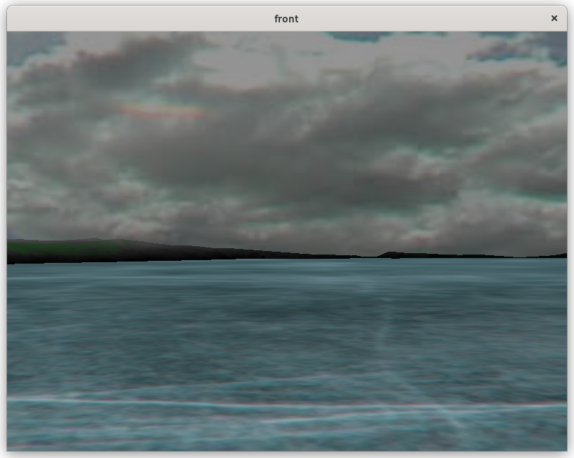
You will also see that the window for the WorldView came up:
Now let's try practicing the DUSIME state machine, by setting DUSIME to "holdcurrent" first (watch out, your simulator motion system starts to move), then run a calibration with the "calibrate" mode (watch out, the controls may be put through their motion range), then start simulating with "advance". Now both your "work" and "advance" buttons are green, and the "hold" button is dark, indicating you can step back to hold at any time.
Since we have not yet connected any dynamics, nothing much happens. We can explore some of the DUECA views to see what the simulation is doing. Open the activity view from DUECA's "View" menu, and press on "update". You should see something like the following:
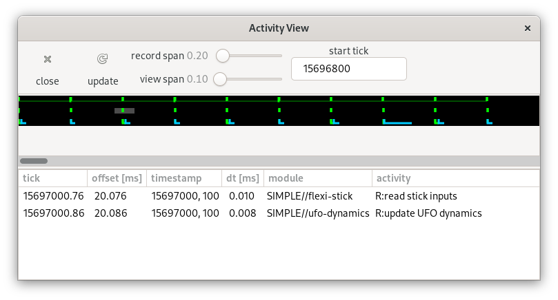
You can select some of the green or blue bars on one of the lines, to see what is happening there. The activity view takes a snapshot of the running DUECA, and shows the timeline for each priority level.
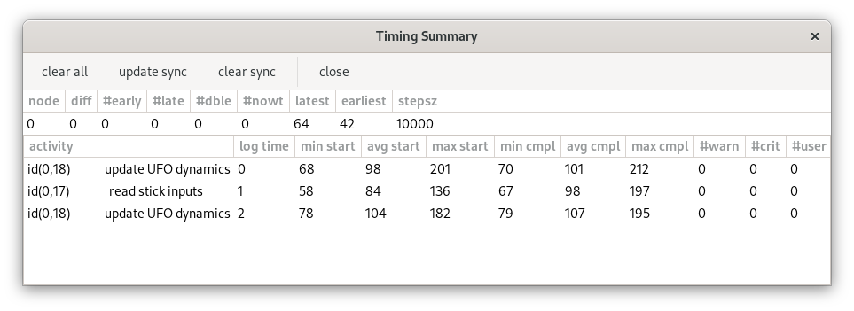
The next view to check is the timing view. You will see, that for lack of real-time priorities and optimization, timing is not perfect. The timing view gives summary statistics for each activity that you requested a timing check on. It also shows, in the top section, the performance of synchronization in different DUECA nodes. The "update sync" button will collect a new synchronization report, "clear sync" clears the early/late counters.
Error messages can be seen in the console where you started dueca, but they are also assembled and collected in the error log view.
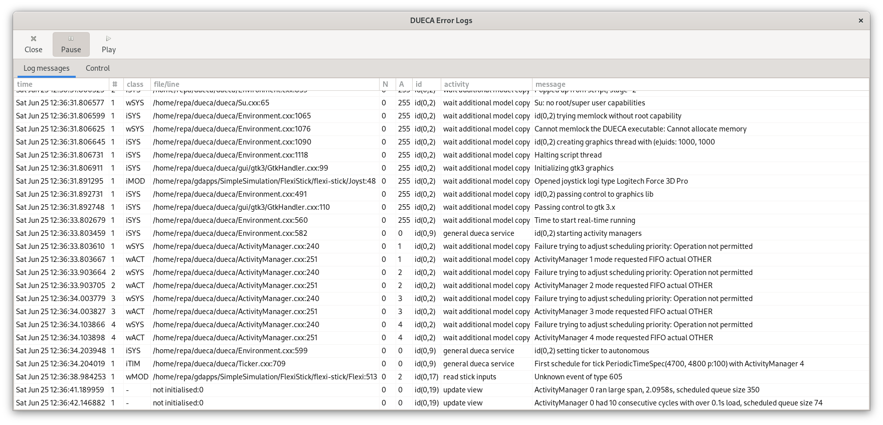
The view lists the time, the class and type of message, node where the message occurred, id of the module or object involved and the activity.
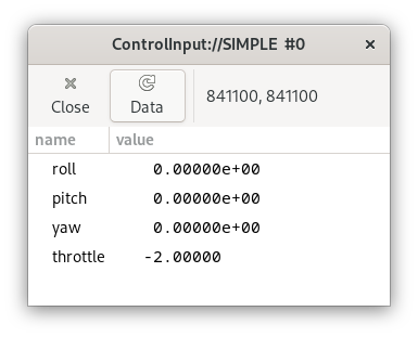
The last view we discuss here is the channel view. This view shows all channels in use in your DUECA process, their entries, who writes these, who reads these, how many points are written and read. For each channel you can also open a specific view to inspect the data there.
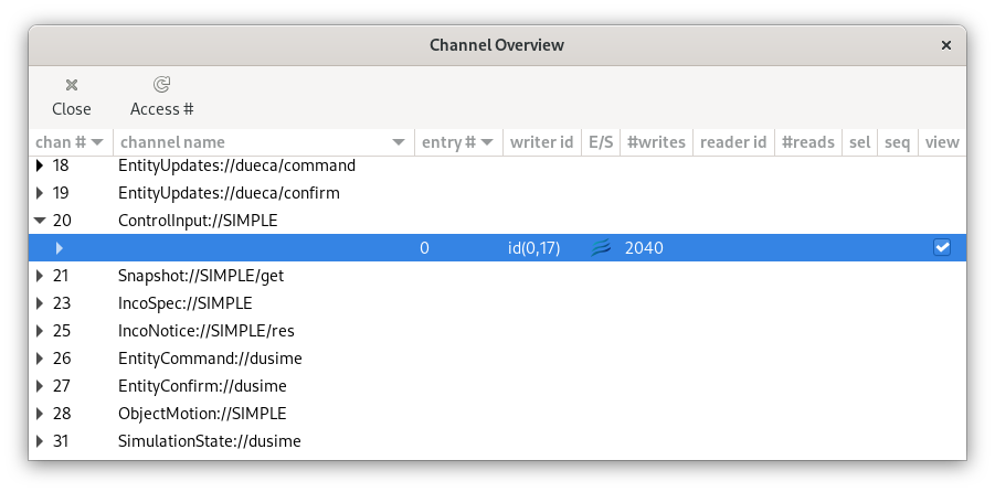
And the detail for a single channel

Log files
After a run, dueca will have left a number of log files in your run folder. You can inspect these at your leasure. One useful thing to do with these logs is to create an overview of your simulation. There is a small script for that:
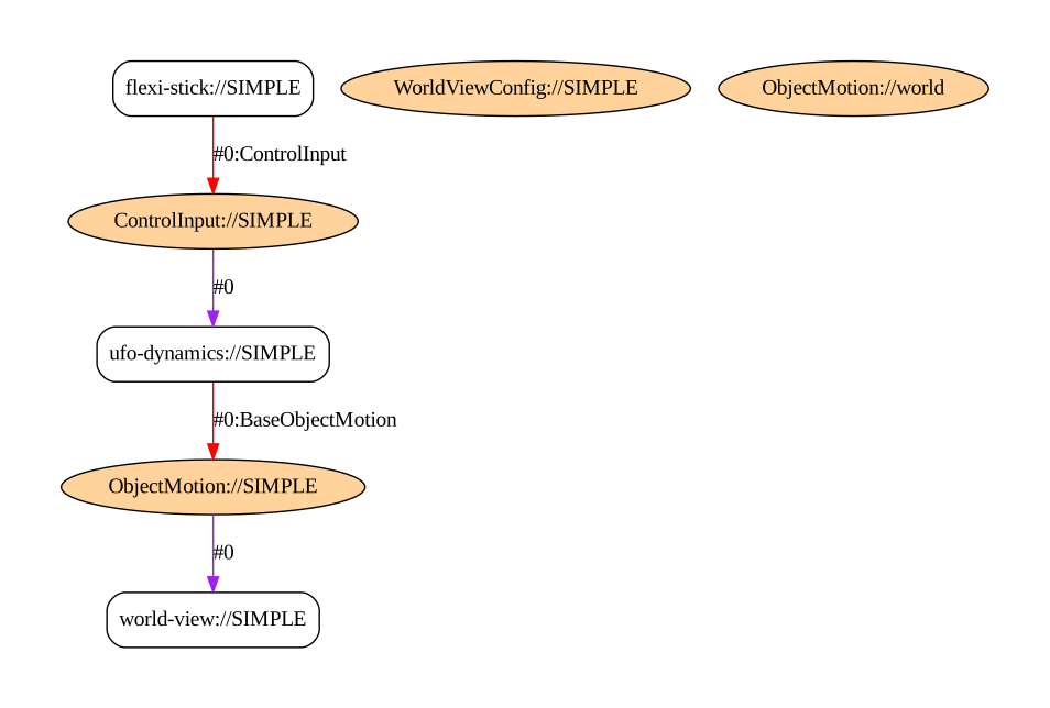
The dueca-channeldot program reads your logs, and produces a file channellayout.pdf. This simulation is still simple, and it has two channels without entries, both from world-view, and the ControlInput:://SIMPLE and ObjectMotion://SIMPLE channels that connect the flexi-stick, ufo-dynamics and world-view modules, here is the channel layout:
Adding dynamics
Let's turn back to the ufo-dynamics module in the UFODynamics.hxx file, and add some dynamics to it. There is an assortment of additional simulation tools in the dueca-extra package, a potluck with some code for numerical integration, calibrating and converting input values, etc. We use the dueca::RigidBody class. You can check out its documentation; it has a state vector with 13 elements. To simplify control, we will specify that rotational moments will be applied on the body until the body rates (p, q, r) follow the stick inputs. Forces are applied until the body velocity in the forward (x) direction follows the joystick input.
Add the dynamics to the header file, first some includes:
And then the additions to the class:
Then initialize in the constructor:
And set the positition of the UFO to somthing reasonable in the constructor body:
In this step, we want to add code to have dynamics, and the output to the WorldView to follow those dynamics. However, we want to also enable snapshot taking and loading, so that an initial state of our dynamics can be stored, and recovered later.
First the dynamics. We can add that in the doCalculation function, at the spot where we read data from the joystick. We create forces from the input and the current linear and rotational velocity, and do an update step with the Runge-Kutta code.
Now the RigidBody object contains the position, orientation and velocities of our UFO, and we can send these to the world-view module. This is placed after the case statement:
To be able to save the state of the RigidBody at the requested moments, we copy the state to an array that has been reserved for that purpose. The snapshotNow function tells the module when that has to be done, so the last part of the doCalculation function is changed to:
The snapshot is stored in that order, because that is also the order of the RigidBody::initialize function. Now we need to ensure that the snapshot will be sent in an appropriate format after it has been made, and that we can restore an initial state from data sent back to the module. The UFODynamics::fillSnapshot function is modified to:
The UFODynamics::loadSnapshot function does the reverse. It will only be called when the simulation is in HoldCurrent mode. The snapshot data is accessed with an AmorphReStore object, which will read the data from the snapshot, and convert it into – in this case – double variables for initializing the model.
You can compile and then again try to run the simulation. You will see that now the viewpoint reacts to inputs on the joystick. As expected, the dynamics don't interact with the ice floor or the hills on the side, however, for the purpose of illustrating development with DUECA, this will be enough. In the following we try to see if what we programmed can be used in combination with DUSIME's record and replay functions.
Initial conditions, recording replay
Set-up
To enable recording and loading initial conditions, in this case the initial state for the UFODynamics module, slightly modify the dueca_mod.py file:
This will expand the View menu of the DUECA window with two items. The reference_file arguments refer to pre-existing files, with initial states and recordings in this case, however we don't have these, so we do without. If later your recordings turn out to have an impressive set of motion traces, you may convert those recordings (initials and recording) as reference files.
Use
Start up the DUECA program, and bring it to hold mode. Now select Initial State -- SIMPLE from the View menu, it will look like this:
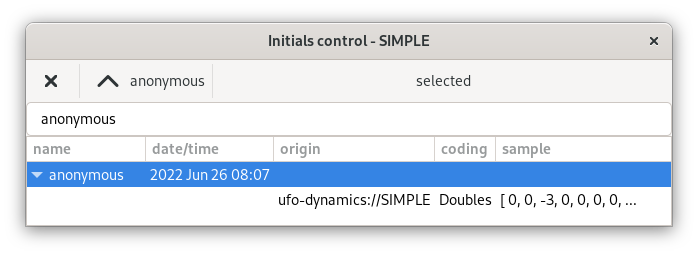
We can now record a "snapshot" of the model state. By filling in an appropriate name in the entry field of the Initials control window, we can give it a name, the default name is anonymous. Once you passed calibrate, the snap button on the DUECA/DUSIME control panel should become active. Press it and see what happens; the image above shows an anonymous snapshot in the list, with a sample of the first bit of data.
When you re-load the initial state, by pressing the up arrow or caret (^) next to the name of the selected state in the menubar, the data is being loaded into the model.
If you want to play around with your model state, you can also try to edit it. In this case, we have chosen to code our snapshot as a list of "double" values, in the fillSnapshot routine:
By clicking on edit with a selected snapshot, a new window will open:
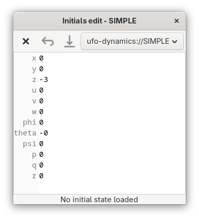
Here you can edit the initial state. If you have (as I have done in the example) added a file for labels named after the module class, in this case ufo-dynamics-labels.txt, the lines in this file are used to label the elements of the snapshot. If you haven't done that, the lines are simply numbered.
When a snapshot has been taken or re-loaded, it will also be possible to record the inputs to the flexi-stick module, and replay these later. Verify that the parameter enable_record_replay = True is set in the parameters for flexi-stick, and that you add a ReplayFiler to the list of objects you want to create, just assign it to a python variable to protect it from the automatic garbage collection in python:
Now open both the initial state window, and the Replay Control window. Toggle the replay control window to the record tab. Bring up DUECA, and control it to pass the calibrate mode. When DUECA/DUSIME is back in hold mode, press the "snap" button to take a snapshot of the initial model state.
Once you have taken a state snapshot, or loaded an existing initial condition, recording your inputs will become possible. Enter a name for your upcoming recording.
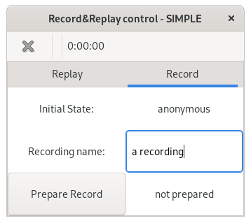
Then press "Prepare record". When you now run the simulation, with advance, the input to the simulation will be recorded. In combination with the initial state recorded in the model snapshot, you now have enough to replay that very same simulation. First select the replay tab in the Replay Control window:
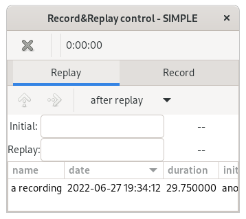
You can now select the created recording. When you do that, you will notice that the window gives you the corresponding initial state, and the recording name. With the up arrow or caret you can load this initial state, and with the right arrow you can prepare the recording for replay. The simulation returns to its starting position, and you can see that now the replay button in the DUECA/DUSIME control panel is active. By pressing the replay button, the simulation starts replaying the previous inputs.
Multiple nodes
So far, we have been running a single DUECA process, in a single computer, probably your development desktop or laptop. DUECA gets really useful if you can deploy the simulation developed on your desktop onto a big simulator, with multiple instrument screens and projectors for the outside view, control devices with control loading (force simulation) and a motion system. To show the principle, let's split off the display from the rest of our simulation, and run two DUECA processes on a single computer. To do this, we need a configuration for a platform, enter your project folder, and enter:
This only added a folder to the run folder. We will define two nodes in this platform, giving them the names of host and igtest. We will assign node number zero to the host node, so the DUECA interface appear there. We will tell it to connect on a host on interface 127.0.0.1, where it will find the "communication master", the computer that will drive the communication cycle.
This creates a new node in the simlab platform. Because we will not be connecting to the outside world, we use the "local" ip address 127.0.0.1. The DUECA interfaces will run here, so we select gtk3 for the graphical user interface back-end. We use the machine class solo, which means that if we check out the code, the dueca-gproject script looks at the modules.xml file in class solo, checking out the full code. That is simply a shortcut, we could make a new machine class that includes everything we had now except for the WorldView modules. There will be some extra code in this DUECA executable that we will not use when running it, but that should be no problem.
For the igtest node, we define a new machine class ig:
This added a folder with files in the .config/class folder. The ig node does not need to run gtk interfaces, so we selected none for the graphical user interface. The modules.xml file for ig is empty, the quickest fix would be to copy the modules.xml file from the solo class, and trim everything there except the world-view modules, so that it looks like:
Now that we have the new machine class, we can create a node for the simulated ig:
Note that here we don't supply the communication master (cmaster), so this node will become the master node for communication. In the configuration file dueca_cnf.py, which you will find in the run/simlab/igtest folder, you can see this in the send_order parameter, which will be set to 0.
Adding these nodes modified the file .config/machinemapping.xml, that file will be used when we ask dueca-gproject to check-out/clone a trimmed copy for deployment on a simulator or other device:
The sparse-checkout flag ensures that not all modules from the SimpleSimulation project will be checked out. For development on solo you do want all modules there, to see and access all code. Then the modules.xml file will determine which of these modules are included in the compilation of the executable.
This also added folders and files to the platform:
The dueca_mod.py listed there is a default dueca_mod.py. However, we just painstakingly added all kinds of configuration to the dueca_mod.py for solo, so let's copy that and adapt it:
There are some tiny changes, definition of the set-up:
We changed the name for node 0 from ecs_node to host_node. This is where we allocate the DUECA interfaces, the joystick interface and the dynamics module. Change all ecs_node to host_node.
Now we can split off the configuration for the outside view, move the ReplayFiler to be in the node 0 if (since it will only be needed there, the ig does not store or reload data), and add the world-view only in the ig node:
There is one final thing we have to change in the dueca_cnf.py for the igtest node. When DUECA starts up on two nodes, our host node will contact the igtest node for instructions on how to further communicate. The default communication is set to UDP Multicast, since that gives good performance on typical simulation set-ups, but this won't work over the localhost (127.0.0.1) interface. We can change the data connection to use websockets:
Now do a git commit -a and celebrate! Let's see if this worked, and pretend we are headed to a simulation facility with multiple computers driving the simulation, and check out / clone our recently developed project:
You now have two compiled DUECA executables, with a new platform, with two nodes. You need two terminal windows to try and run this. Also, I forgot about the links.script for the ig node. We should copy over the links.script from solo and commit that, otherwise there is no access to the graphics files.
Terminal 1
While this executable is anxiously waiting for colleague DUECA's to join it, hop over to the other terminal, and start there:
Terminal 2
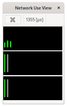
In the logs written to the terminal you will see the two DUECA executables connecting, and then synchronizing to each other's timing. The DUECA/DUSIME control panel now shows the two nodes, and the Entities overview indicates which module runs where; in this case only the world-view runs in node 1. There is a neat little additional window in the view menu, the Net Use View. It shows a histogram for timing and for occupancy of the network messages.
Everything should now work as before, but the Activity View has an additional set of lines for the second node, and the Timing View shows a line on the synchronization of the second node.